
Choosing the right CPO/NPO FAU starts with the optical engine, not a catalog page. Co-packaged optics and near-packaged optics place optical components close to switching silicon, but their packaging and integration needs can differ. The FAU, or fiber array unit, provides the physical path between fibers and optical interfaces. A small alignment error can affect coupling efficiency, while a poorly matched fiber pitch can complicate assembly. Details matter.
A practical selection compares channel count, fiber type, pitch, insertion loss, return loss, and alignment tolerances against the system design. Check how the FAU handles thermal cycling, vibration, and repeated manufacturing steps. Ask suppliers for measured performance, test conditions, and process-control data—not just a headline specification. Good evidence is specific. It shows how samples were built and tested.
Manufacturability deserves equal attention. A design that performs well in a lab may be harder to align at production scale. Review connector access, adhesive or bonding methods, inspection requirements, and repair strategy with packaging and assembly teams. These choices can affect yield, serviceability, and long-term reliability. No single FAU fits every optical platform. The trade-offs are real.
This guide outlines how to compare CPO/NPO FAU options, assess supplier claims, and connect component specifications to application needs. Some requirements may remain uncertain early in a project. That is worth admitting. Teams should document assumptions, validate prototypes under representative conditions, and revisit the choice as the optical engine and manufacturing process mature.
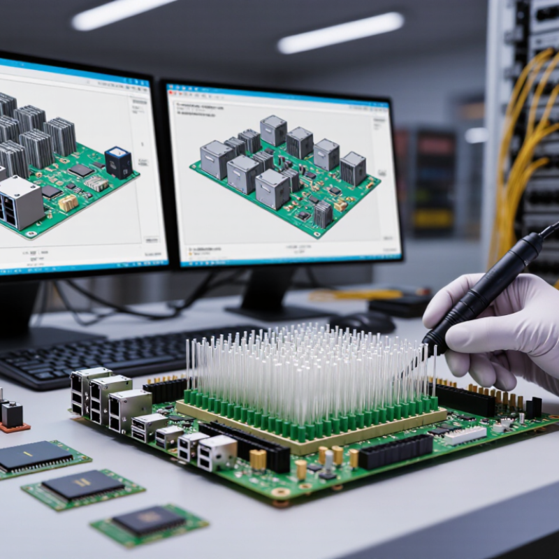
CPO, NPO, and FAU describe different parts of an optical network. CPO means co-packaged optics: optical engines sit within the same package as switching silicon, reducing the distance electrical signals travel. NPO means near-packaged optics. Its optical engine sits outside, but close to, the main package; exact definitions can vary across technical discussions.
An FAU, or fiber array unit, is a precision assembly that holds fibers at fixed spacing and aligns them with an optical interface. It is a component, not an architecture. Tiny alignment errors matter.
The International Energy Agency’s Energy and AI report estimates data centres used about 415 TWh of electricity in 2024, around 1.5% of global consumption. It projects demand could reach about 945 TWh by 2030. These figures explain the pressure to improve efficiency, but they do not prove that CPO alone reduces a complete system’s energy use. Compare power, cooling, fiber access, repairability, and manufacturing yield together. A trade-off remains. CPO can shorten electrical paths, yet make servicing less straightforward; NPO may offer a more accessible compromise. Measure the actual system, not just the optical link.
How to Choose the Right CPO NPO FAU for Optical Networking?
How CPO, NPO, and FAU Differ in System Architecture
CPO places optical engines beside a switching ASIC within the same package or package assembly. This shortens electrical paths, helping support high bandwidth density and lower signal loss. It also brings optics close to heat-producing electronics. Cooling, fiber routing, and field replacement need careful planning. NPO positions optical engines near the ASIC, but outside its package. Electrical paths are longer than in CPO, yet the separate placement can make access and thermal management more practical. The exact boundary of “near” varies by design, so compare actual layouts rather than labels alone.
An FAU, or fiber array unit, is different: it aligns and holds multiple fibers for connection to an optical device. It is a component, not a system-level placement architecture like CPO or NPO. A design may use an FAU with either approach. This distinction is easy to blur. It matters when teams compare integration, maintenance, and optical coupling needs. There is no universal winner; deployment scale, power limits, service access, and required bandwidth all shape the choice.
Tips: Ask for a package cross-section and fiber-routing drawing. Check how technicians would replace an optical engine, and where heat leaves the assembly. Small details matter. If the supplier’s architecture terms remain vague, request measurable distances between the ASIC, optical engine, and fiber interface.
| Comparison Dimension | CPO (Co-Packaged Optics) | NPO (Near-Packaged Optics) | FAU (Fiber Array Unit) |
|---|---|---|---|
| What it is | A system architecture that places optical engines in the same package or package-level assembly as a switching or computing ASIC. | A system architecture that places optical engines close to an ASIC, but outside its package. | A passive optical component that holds and aligns multiple fiber ends to an optical interface; it is not, by itself, a system architecture. |
| Primary role | Moves optical conversion close to the ASIC to reduce the length of high-speed electrical connections. | Shortens electrical connections compared with front-panel pluggable optics while keeping the optical engine separate from the ASIC package. | Provides accurate, stable fiber positioning and optical coupling to a photonic chip, optical engine, or other optical interface. |
| Optical-engine location | Within the ASIC package or a closely integrated package assembly. | On the same board or module near the ASIC, but in a separate package or assembly. | Not applicable. An FAU may be used to connect fibers to optical engines in different architectures. |
| Electrical interconnect | Typically the shortest of the three system-level arrangements because the optical engine is package-adjacent to the ASIC. | Shorter than a conventional front-panel pluggable connection, but generally longer than a connection within a co-packaged assembly. | Does not define the electrical path between an ASIC and an optical engine. |
| Fiber interface | Fibers are routed to optical engines near the ASIC package; an FAU can be part of the fiber-coupling solution. | Fibers connect to the nearby optical engine; an FAU may be used to align and couple them. | Typically presents a precisely arranged set of fibers for coupling to an optical device or photonic integrated circuit. |
| Thermal and service considerations | Requires careful thermal design near the ASIC. Package integration can make optical-engine replacement more involved than replacing a front-panel module. | Provides physical separation from the ASIC package, which can allow more independent placement and service planning than CPO. | Requires mechanical stability, accurate alignment, and protection of the fiber interface; it does not determine system-level serviceability. |
| Typical design priority | Reducing electrical reach and supporting high aggregate bandwidth in dense systems. | Balancing shorter electrical paths with separation between the ASIC package and optical engine. | Achieving reliable, repeatable fiber-to-device alignment and coupling. |
| Key trade-off | Greater package and fiber-integration complexity, with potentially more demanding maintenance and thermal planning. | Still requires careful high-speed electrical and optical integration, while retaining more separation than CPO. | Alignment accuracy and handling are critical; an FAU does not replace the choice between CPO, NPO, or other system architectures. |
| When to consider it | When minimizing electrical interconnect distance and integrating optics closely with the switching or computing package are key requirements. | When optics should be close to the ASIC but remain outside its package for system-integration or service-planning reasons. | When a design needs a structured, accurately aligned multi-fiber interface to an optical device or engine. |
Important distinction: CPO and NPO describe where optical engines are positioned relative to an ASIC. FAU describes a fiber-alignment component that can support either architecture. The best choice depends on electrical reach, packaging, thermal management, fiber routing, and service requirements.
How to Choose the Right CPO NPO FAU for Optical Networking?
Which Network Requirements Shape the Choice
Start with bandwidth density, link distance, power limits, and service access. The Ethernet Alliance’s 2024 Ethernet Roadmap covers 800GbE and 1.6TbE links, reflecting the push toward higher port capacity. A network built for dense AI clusters may favor co-packaged optics (CPO), where optical engines sit close to the switch ASIC. Shorter electrical paths can help manage signal loss and power. But repairs may involve more than swapping a front-panel module. That trade-off matters.
Near-packaged optics (NPO) keeps optics close to the ASIC while allowing more service flexibility. It may suit operators who need high bandwidth but want easier component replacement. Power deserves a close look: the International Energy Agency’s Electricity 2024 report says data centres, AI, and cryptocurrency used about 460 TWh in 2022, with demand potentially exceeding 1,000 TWh by 2026. Every watt counts. A fibre array unit (FAU) is different: it aligns multiple fibres with an optical interface, so fibre count, pitch, connector access, and alignment tolerance shape its selection. In the lab, test the actual fibre routing and thermal conditions, not just a clean diagram. I would not choose CPO on density alone; the maintenance plan can change the answer. The messy part is that requirements often shift after deployment.
How to Choose the Right CPO NPO FAU for Optical Networking?
Compare CPO and NPO as integration approaches, but treat the FAU as a component, not a competing architecture. That distinction matters. CPO places optical engines close to the switch ASIC, while NPO locates them nearby with more separation. Designs vary, so check actual specifications rather than relying on labels. Compare bandwidth, latency, power consumption, and optical insertion loss under the same operating conditions. A strong lab result can shift with temperature or fiber routing. Small differences matter.
Reliability depends on more than headline performance. Review thermal test results, channel-to-channel loss variation, and alignment stability across the expected operating range. For an FAU, ask how assembly tolerances and fiber handling affect repeatability. For CPO and NPO systems, examine cooling needs, access for repairs, and the consequences of replacing an optical engine. Integration deserves equal attention: confirm fiber routing, bend-radius limits, electrical interfaces, and compatibility with the intended switch platform. A compact layout may save space but complicate service. I would not assume the densest design is always the easiest to maintain.
Tips: Request test data from a representative system, not just a component. Compare like with like, and document the conditions. If service procedures are unclear, ask for a hands-on review before committing.
Compare performance, reliability, and integration by looking at where the optics sit and how they are serviced.
How to read this: Scores are qualitative design tendencies on a 1–5 scale, not measured product benchmarks. Higher scores indicate more of the stated characteristic. Actual performance and reliability depend on implementation.
FAU note: A fiber array unit is a passive fiber-alignment and coupling component, not an alternative to CPO or NPO. Evaluate its channel count, insertion loss, alignment tolerance, and environmental stability within the chosen optical architecture.
Start with the deployment, not the acronym. CPO places optical engines close to switching silicon, supporting high bandwidth density and shorter electrical paths. It may suit tightly integrated systems where power and front-panel space are constrained. Yet servicing can be less straightforward: a failed optical engine may involve work on a larger assembly. NPO keeps optics nearby but more separable, offering a practical middle ground when teams need dense links and manageable replacement. There is no universally clean answer. Rack access, airflow, and maintenance windows matter as much as peak throughput.
Treat the FAU as an interface choice, not a competing system architecture. Its fiber arrangement, pitch, channel count, and alignment tolerance must fit the optical engine and installation process. For frequent module changes, favor a connection approach technicians can inspect and reseat without disturbing neighboring fibers. For fixed, high-density assemblies, compact routing may matter more, but bend radius and strain relief still need checking. Not just bandwidth. Measure actual link distances, connector loss, thermal conditions, and expected upgrade cycles before selecting. A lab demo can hide awkward cable paths. I would verify the assembly in the intended chassis and service procedure. That step is easy to skip, and costly to regret.

Sign up for our mailing list to stay informed and up to date with our latest news and products!
(905) 832 – 0600
2175-A Teston Road
Maple, Ontario
L6A 1T3
(780) 451 – 0238
24790 – 117 Avenue
Acheson, Alberta
T7X 6C2
(604) 882 – 1564
9511 – 194A Street
Surrey, British Columbia
V4N 4G4
(306) 955 – 6005
3926 Arthur Rose Avenue Saskatoon, Saskatchewan
S7P 0C9
(450) 687 – 2721
2750 Rue Bernard-Lefebvre
Laval, Quebec
H7C 0A5