What Is a Festo Pneumatic Cylinder and How Does It Work?
A Festo Pneumatic Cylinder converts compressed-air energy into controlled linear motion. Inside its metal or polymer body, air pressure pushes a piston, while the piston rod transfers force to a machine component. Directional valves manage air entry and exhaust. The result is a repeatable push, pull, clamp, lift, or positioning action.
This technology remains relevant as factories pursue faster and more flexible automation. The International Federation of Robotics reported 541,302 industrial robots installed worldwide in 2023, showing sustained investment in automated production. Pneumatic actuators often support these systems because they are compact, fast, and comparatively simple to maintain. Festo’s cylinder ranges commonly align with ISO 15552 dimensions, helping engineers select compatible mounting accessories and replacement components. That standardization matters beside a conveyor, where a few millimeters of misalignment can create vibration, wear, or unexpected downtime.
Understanding the working cycle requires more than reading a catalogue rating. Force depends on pressure, piston area, friction, and the opposing load. Speed depends on airflow, valve capacity, tubing length, and exhaust control. In practice, a cylinder may perform differently during cold starts or when moisture enters the air line. Small details matter. The wrong cushioning setting can make the rod strike its end cap sharply. The correct model should therefore be chosen through load calculations, duty-cycle checks, air-quality review, and hands-on testing. This article explains how a Festo Pneumatic Cylinder works, where it fits in industrial automation, and why real operating conditions can challenge simplified specifications.
What Is a Festo Pneumatic Cylinder?
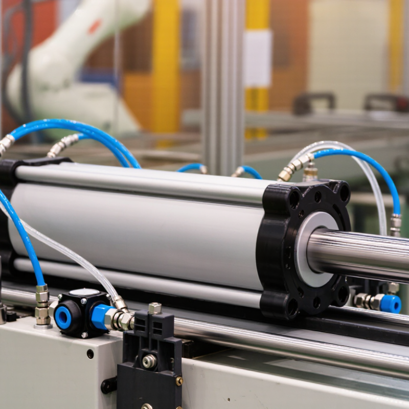
A pneumatic cylinder is a mechanical actuator that converts compressed air into straight-line motion. It usually contains a sealed tube, piston, piston rod, end caps, and internal seals. When air enters one side, pressure pushes the piston forward. Air entering the opposite side retracts it. This movement can clamp, lift, push, pull, or position a machine component.
The cylinder does not create force by itself. Its output depends on air pressure, piston diameter, friction, and load resistance. A larger piston usually produces greater force, but it also consumes more air. In workshops, technicians check rod alignment and seal condition before installation. Misalignment can cause uneven wear, air leakage, or early failure. Choosing a cylinder is not always straightforward. Speed, stroke length, mounting space, and operating environment must all match the application. A simple calculation helps, but real machines can behave differently.
Tips: Use clean, dry, regulated air. Confirm the required stroke and load before purchasing. Install flow controls near the cylinder ports for smoother movement. Listen for hissing sounds during testing. They often indicate leakage. Inspect the rod for scratches and keep it free from dust. One detail is easy to overlook: excessive speed can damage seals, even when the cylinder appears correctly sized.
Core Components and Their Functions
A pneumatic cylinder converts compressed air into controlled linear motion. Its barrel contains the working chamber, while a piston divides that chamber into two air spaces. When air enters one port, pressure pushes the piston forward. Air leaves through the opposite port, allowing the rod to extend. Reversing the air supply retracts the rod. The result looks simple, but reliable movement depends on several small components.
The piston rod transfers force to a machine part, such as a clamp or slide. Seals around the piston and rod prevent air leakage and keep contaminants outside. End caps close the barrel and usually contain the air ports. Some cylinders include internal cushioning, which slows the piston near each stroke end. This reduces impact, noise, and wear. Mounting hardware also matters. A misaligned bracket can create side loads, even when the cylinder appears correctly installed.
In field inspections, I check the rod surface, fittings, and exhaust sound before replacing parts. A faint hiss may indicate a worn seal, loose tube, or damaged port thread. Pressure alone does not prove proper operation. The cylinder may move, yet stall under load because friction or alignment is poor. This is where diagnosis can become imperfect. Temperature, lubrication, and cycle frequency also influence service life. Clean, dry air and correctly rated components provide more dependable performance. Small details matter.
How Compressed Air Produces Linear Motion
A pneumatic cylinder converts compressed air into controlled linear motion. It contains a sealed barrel, a piston, and a rod connected to the working load. When compressed air enters one side, pressure pushes against the piston surface. The piston then moves, carrying the rod forward or backward. Air does the pushing.
Directional valves control which chamber receives air. To extend the rod, the valve sends air behind the piston. To retract it, the valve redirects air to the opposite chamber. Exhaust air leaves through a separate port, often with a flow control device. Adjusting this airflow changes the movement speed. The pressure determines available force, while the piston diameter affects how much force the cylinder can produce.
In practical equipment, mounting alignment matters greatly. A side load can wear the rod seal and cause uneven travel. Small leaks matter. They increase compressor workload and may create slower, weaker movement. Clean, dry air usually protects internal parts, although maintenance requirements vary with temperature, dust, and duty cycle. I have found that many motion problems are blamed on the cylinder too quickly. A restricted tube, loose fitting, or poorly adjusted valve may be the real cause. Pneumatic motion also has limits: trapped air can make the rod springy, and precise positioning may require additional control components. It is simple, but not always exact.
Types and Selection Factors of Festo Cylinders
Pneumatic cylinders convert compressed air into controlled linear motion. Rod cylinders suit pushing, clamping, and lifting, while rodless cylinders save space along longer travel paths. Compact cylinders fit tight assemblies. Guided cylinders resist rotation and side loads more effectively. Rotary actuators handle limited angular movement.
Selection should begin with load, stroke, speed, and mounting position. The required force depends on pressure, piston area, and friction. For a horizontal slide, engineers should include acceleration and guide resistance. A practical safety factor of 1.3 to 2.0 is common, but oversized cylinders waste air. The U.S. Department of Energy reports that compressed-air systems can consume 10% to 15% of industrial electricity. Leakage may waste 20% to 30% of compressor output. Efficient sizing matters.
Air quality also affects service life. Water separators, suitable filtration, and correct lubrication may protect seals and valves. In dusty areas, rod protection and robust mounting deserve closer attention. ISO 15552 dimensions can simplify interchangeability across standard cylinder designs. Yet standards do not guarantee identical performance. This is where many selections go wrong. Catalog force is not real machine force. Temperature, cushioning, side loading, and cycle frequency can change results. A short test under actual operating conditions often reveals more than a spreadsheet. Technician feedback should remain part of the decision, even when the calculation looks perfect.
Installation, Control, and Routine Maintenance
What Is a Pneumatic Cylinder and How Does It Work?
A pneumatic cylinder converts compressed air into linear motion. During installation, mount the cylinder squarely with the driven load. Misalignment can bend the rod or wear the seals. Use flexible tubing, clean fittings, and an air filter near the inlet. Check that the operating pressure matches the cylinder’s rated range. Do not force the rod by hand.
Keep it aligned.
Control depends on the valve, regulator, and flow controls. A directional valve sends air to either side of the piston. A regulator adjusts force and speed by changing air pressure. Flow controls should be adjusted gradually, especially during the first test cycle. Excessive speed may cause harsh impacts at the stroke ends. Built-in cushioning can reduce this shock, but it cannot correct poor alignment.
Routine maintenance should include checking air leaks, loose mounting bolts, damaged tubing, and rod contamination. Apply only the lubricant recommended for the cylinder and air system. Too much oil may damage seals or enter nearby equipment. Drain moisture from the air preparation unit regularly. Inspect the rod surface for scratches and corrosion. I have seen small leaks remain unnoticed because machines still completed their cycles. That assumption is risky. Record pressure readings, cycle behavior, and inspection dates. A checklist helps, although it can still miss a worn seal during a quick inspection. Listen for hissing and watch for slower movement. These simple observations often reveal trouble before production stops.