
Choosing a reliable PCB manufacturer for DC fast charging equipment requires more than comparing prices or production volume. High-power chargers face continuous electrical stress, heat buildup, vibration, and demanding safety expectations. Their circuit boards must support stable current delivery, accurate monitoring, insulation control, and dependable communication between power modules. A weak board design can cause overheating, charging interruptions, or expensive field repairs.
This guide introduces 10 Best PCB Manufacturers for DC Fast Chargers, focusing on capabilities that matter in real projects. These include multilayer PCB production, heavy copper options, thermal management, controlled impedance, automated optical inspection, and electrical testing. Experience with automotive, industrial, and energy applications also deserves careful attention. Manufacturing certifications, traceability systems, engineering support, and documented quality procedures can reveal whether a supplier is prepared for long-term production.
The phrase PCB for DC Fast Chargers covers more than a standard control board. It may include power, protection, sensing, communication, and interface circuits operating inside a compact enclosure. Details matter. A board that performs well in a laboratory may behave differently beside a hot power module for twelve hours. That concern is easy to overlook. The manufacturers discussed here are evaluated through practical, technical, and reliability-focused criteria, rather than marketing claims alone. However, no ranking fits every project. Material choices, operating voltage, order volume, certification needs, and regional support can change the best decision. Readers should verify current capabilities, sample results, and compliance documents directly before placing production orders. Mistakes happen. Careful validation remains essential.
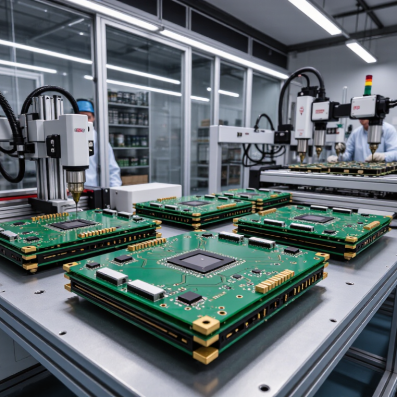
A PCB manufacturer for DC fast chargers produces the circuit boards that control high-power charging equipment. These boards route electricity, manage signals, and connect sensors, relays, displays, and communication modules. Unlike ordinary consumer PCBs, charger boards must handle heat, vibration, moisture, and rapid electrical changes. A capable manufacturer understands creepage distance, insulation requirements, thermal design, and high-current copper structures. They should also support prototype development, design-for-manufacturing reviews, and controlled production records.
In practical projects, engineers examine copper thickness, laminate performance, connector strength, and coating quality. They also expect electrical testing, automated optical inspection, and traceable component sourcing. A reliable factory can provide test reports and explain failure risks without hiding uncomfortable details. Certification support matters, but certification alone proves little about long-term field performance. A board may pass a laboratory test and still fail near a dusty roadside cabinet. That possibility deserves honest review.
Tips: Ask how the manufacturer tests thermal cycling, insulation resistance, and high-current joints. Request sample data, not only polished claims. Check whether engineers can revise layouts after testing. Small design mistakes often appear during assembly, not on a computer screen. Leave room for inspection and repair. Even experienced teams miss something sometimes; a careful manufacturer documents the lesson and improves the next batch.
A PCB manufacturer for DC fast chargers produces the circuit boards used in power conversion, charging control, communication, protection, thermal monitoring, and user-interface systems. The chart below shows representative DC fast-charging power classes and their approximate output current calculated using current = power ÷ voltage.
Values are representative engineering reference points rather than company specifications. Actual charger ratings vary by electrical architecture, cooling method, connector limits, grid input, and applicable safety standards. Approximate current values are calculated at nominal output voltage before conversion losses.
10 Best PCB Manufacturers for DC Fast Chargers
Key PCB Requirements in DC Fast Charging Systems
A DC fast charger PCB must handle high current without creating dangerous heat. Copper thickness, trace width, and connector design directly affect current capacity. In practical inspections, narrow power traces often show discoloration near terminals. That detail matters.
Thermal management needs more than a metal heat sink. The board should use suitable materials, thermal vias, and carefully positioned temperature sensors. High-power switching devices require short current paths and low parasitic inductance. A thicker copper layer helps, but it is not automatically better. Designers must verify weight, cost, and manufacturing limits.
Safety distances are equally important. Adequate creepage and clearance reduce risks during high-voltage operation, humidity, and contamination. The PCB should support reinforced insulation, isolation barriers, surge protection, and controlled grounding. These features need testing, not assumptions. Electromagnetic interference also deserves early attention. Filter placement, shielding, and return paths can prevent unstable charging behavior.
Reliable production requires traceable materials and consistent inspection. Manufacturers should provide electrical testing, thermal cycling data, and documented process controls. Standards-based verification improves confidence, although paperwork alone cannot reveal every field failure. Real testing under heat, vibration, dust, and repeated charging cycles remains essential. Sometimes, the first design passes laboratory checks but struggles inside a compact charger cabinet. That gap deserves honest review.
Selecting the ten best PCB manufacturers for DC fast chargers requires more than comparing unit prices. A charger PCB may carry high current while switching rapidly inside a warm enclosure. Ask each manufacturer for evidence of thermal design experience, controlled impedance, copper weight, and creepage planning. Request sample cross-sections, not only polished photographs. Look for inspection records, traceability, and documented engineering changes. Small details matter. A missing revision record can delay a field repair.
Evaluate process capability at the factory floor. Confirm whether automated optical inspection, X-ray inspection, solder-paste measurement, and functional testing are performed on your actual board type. Ask for measured data from pilot runs. Cp and Cpk values can reveal unstable dimensions or plating thickness.
For power boards, inspect via design, barrel copper, pad balance, and heat-spreading paths. Thermal cycling, vibration, humidity, and high-voltage insulation tests should match the charger’s operating environment. Certifications support trust, but certificates alone prove little.
A reliable manufacturer also communicates clearly when a design is weak. During a technical review, ask how they handle warped boards, counterfeit components, and late material substitutions. Confirm approved suppliers and lot-level records before production begins. Visit the site if possible. Observe storage discipline and operator training. I would not ignore an awkward answer. It may expose a real gap. A perfect checklist does not exist; even experienced teams can overlook connector heating or contamination under a power module. Compare response time, corrective-action quality, and repeatability across suppliers. Price belongs in the decision, but it should not lead it.
Choosing among the 10 leading PCB manufacturers for DC fast chargers requires more than comparing prices. These boards handle high current, rapid switching, heat, and repeated charging cycles. Experienced buyers examine copper weight, thermal design, creepage distance, and insulation performance. A strong manufacturer should support multilayer layouts, controlled impedance, and stable production at scale. Details matter. A poorly managed via can become a hot spot near a power module.
The best candidates provide engineering records, material certificates, and lot-level traceability. They use automated optical inspection, electrical testing, and X-ray checks when hidden joints require verification. For DC chargers, thermal cycling and high-voltage tests reveal weaknesses that visual inspection may miss. I would also review solder mask quality, connector alignment, and surface finish consistency. Factory audits offer useful evidence. However, a polished audit report cannot replace samples tested under realistic load.
Each of the ten leading PCB manufacturers should explain its response to design changes, field failures, and urgent replacement needs. Clear communication often protects a project better than a low quotation. Reliability also depends on the charger design, assembly process, and maintenance conditions, not only the bare board. No supplier is perfect. Even a qualified factory may miss a defect or underestimate thermal stress. That uncomfortable possibility deserves documented testing, independent review, and honest revision before production.
Choosing among the 10 best PCB manufacturers for DC fast chargers requires more than comparing prices. Quality starts with stable copper thickness, clean plating, controlled impedance, and strong solder joints. High-current charger boards often face heat, vibration, and repeated power cycles. Experienced manufacturers should provide thermal cycling data, automated optical inspection, and electrical test records. X-ray inspection also matters for hidden joints and dense power modules. I would ask for traceability from raw laminate to final shipment. A polished certificate is useful, but production evidence is stronger.
Tips: Request sample boards before signing a large order. Compare copper weight, layer alignment, hole quality, and surface finish under magnification. Ask how rejected boards are recorded and corrected. Small details expose weak process control.
Technology and production capability must be judged together. Heavy-copper and multilayer designs can improve current handling, but they require accurate etching and reliable lamination. Some factories support rapid prototypes yet struggle with consistent volume output. Others offer impressive machinery but limited engineering feedback. That difference can affect charger uptime. Review DFM reports, first-pass yield, capacity planning, and change-control procedures. I once underestimated inspection time; the board passed basic testing but showed thermal stress during extended operation. That mistake changed my evaluation method. Reliable suppliers explain failures openly and improve the process.
| Manufacturer Profile | Primary PCB Focus | Layer Capability | High-Current Features | Materials & Thermal Options | Quality Standards | Production Scale | Typical Prototype Lead Time | DC Fast-Charger Suitability |
|---|---|---|---|---|---|---|---|---|
| Profile 01 | High-reliability multilayer Power-control and charger-management boards | 2–32 layers Fine-line multilayer capability | Heavy copper up to 6 oz; plated through-holes; large current-carrying planes | High-Tg FR-4; halogen-free options; aluminum-backed thermal boards | IPC-6012 Class 2/3; IPC-A-600 inspection; AOI and electrical testing | Prototype to high-volume production | 5–10 working days | ★★★★★ Excellent for power modules and control systems |
| Profile 02 | Power electronics Rectifier, inverter, and PFC assemblies | 1–24 layers Mixed rigid and rigid-flex production | 2–5 oz copper; thermal vias; isolated high-voltage sections | High-Tg FR-4; metal-core PCB; thermal-management laminates | IPC-6012; IPC-A-610 assembly support; ISO 9001 quality system | Medium to high volume | 7–12 working days | ★★★★★ Strong for AC/DC conversion and power distribution |
| Profile 03 | Automotive-grade PCB Charging-interface and vehicle-communication circuits | 2–20 layers High-density interconnect options | Controlled impedance; creepage and clearance design support; copper-filled vias | Automotive-qualified laminates; high-Tg and low-loss materials | IATF 16949; ISO 9001; IPC-6012; PPAP documentation capability | High-volume automotive production | 8–15 working days | ★★★★★ Best suited to vehicle-side and safety-critical electronics |
| Profile 04 | Quick-turn engineering Prototype and pilot boards for charger development | 1–16 layers Rigid, flex, and rigid-flex options | Up to 4 oz copper; via-in-pad; press-fit and connector-ready layouts | Standard and high-Tg FR-4; polyimide flex materials | ISO 9001; IPC-A-600 inspection; automated optical inspection | Prototype and low-to-medium volume | 2–7 working days | ★★★★☆ Ideal for early-stage charger testing and validation |
| Profile 05 | Thermal-management PCB High-power semiconductor and charging modules | 1–12 layers Single- and multilayer metal-core boards | Heavy copper; insulated metal substrate; thermal-via arrays | Aluminum and copper metal-core PCB; thermally conductive dielectrics | IPC-6012; UL-recognized materials; thermal and dielectric testing | Medium-volume specialized production | 10–18 working days | ★★★★★ Highly suitable for heat-generating switching devices |
| Profile 06 | High-density interconnect Control, sensing, display, and communication boards | 2–28 layers Microvia and sequential-build capability | Fine-pitch BGA support; controlled impedance; embedded copper planes | Low-loss laminates; high-Tg FR-4; halogen-free materials | IPC-6012; IPC-2221 design guidance; automated electrical testing | Medium to high volume | 7–14 working days | ★★★★☆ Strong for compact monitoring and communications electronics |
| Profile 07 | Safety-critical power PCB Protection, isolation, metering, and supervisory circuits | 2–20 layers High-voltage layout capability | Extended creepage and clearance; slots; conformal-coating preparation | High-Tg FR-4; CTI-rated laminates; flame-retardant materials | ISO 9001; IPC Class 3 capability; UL-related design and material controls | Medium to high volume | 8–16 working days | ★★★★★ Suitable for protection and isolation functions |
| Profile 08 | Flexible interconnect Compact human-machine interfaces and sensor harnesses | 1–12 layers Flex and rigid-flex construction | Flexible copper circuits; stiffeners; selective gold contacts | Polyimide; adhesive-free flex materials; high-temperature coverlay | IPC-6013; IPC-A-600; bend-cycle and continuity testing | Prototype to medium volume | 10–20 working days | ★★★☆☆ Useful for compact auxiliary and interface assemblies |
| Profile 09 | Cost-optimized volume PCB Standardized charger-control and auxiliary power boards | 2–16 layers Standard multilayer production | 1–3 oz copper; plated slots; standard thermal-via structures | FR-4; high-Tg options; lead-free compatible finishes | ISO 9001; IPC-6012; AOI, flying-probe, and electrical testing | High-volume production | 10–20 working days | ★★★★☆ Good for standardized products where cost efficiency matters |
| Profile 10 | Integrated PCB assembly Turnkey boards for charger control and power-management systems | 2–24 layers PCB fabrication and SMT/THT assembly | Heavy-copper options; press-fit terminals; selective soldering | High-Tg FR-4; metal-core options; conformal-coating support | ISO 9001; IPC-A-610; J-STD-001; traceability and functional testing | Prototype through high volume | 7–15 working days | ★★★★★ Effective for reducing supplier count and integration time |

Sign up for our mailing list to stay informed and up to date with our latest news and products!
(905) 832 – 0600
2175-A Teston Road
Maple, Ontario
L6A 1T3
(780) 451 – 0238
24790 – 117 Avenue
Acheson, Alberta
T7X 6C2
(604) 882 – 1564
9511 – 194A Street
Surrey, British Columbia
V4N 4G4
(306) 955 – 6005
3926 Arthur Rose Avenue Saskatoon, Saskatchewan
S7P 0C9
(450) 687 – 2721
2750 Rue Bernard-Lefebvre
Laval, Quebec
H7C 0A5